𐄀 Technologie verbindung zur Zukunft


Elektrische schematische Darstellung
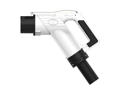
Modell details des YG 762 DC-Fahrzeug verbinders (diese Spezifikation gilt für das Modell in der folgenden Tabelle): | |||||||||||
Nein. | Name | Hafen verkabelung spezifikation (mm²) | |||||||||
DC | DC- | PE | A | A- | CC1 | CC2 | S | S- | |||
1 | Der YGC762-EV-P9P-80 Stecker | 20 | 20 | 25 | 4 | 4 | 0,75 | 0,75 | 0,75 | 0,75 | |
2 | Der YGC762-EV-P9P-125 Stecker | 35 | 35 | 25 | 4 | 4 | 0,75 | 0,75 | 0,75 | 0,75 | |
3 | Der YGC762-EV-P9P-160 Stecker | 50 | 50 | 25 | 4 | 4 | 0,75 | 0,75 | 0,75 | 0,75 | |
4 | Der YGC762-EV-P9P-200 Stecker | 70 | 70 | 25 | 4 | 4 | 0,75 | 0,75 | 0,75 | 0,75 | |
5 | YGC762-EV-P9P-250 Stecker | 80 | 80 | 25 | 4 | 4 | 0,75 | 0,75 | 0,75 | 0,75 | |
6 | Der YGC762A-EV-P9P-125 Stecker | 35 | 35 | 25 | 4 | 4 | 0,75 | 0,75 | 0,75 | 0,75 | |
7 | Der YGC762A-EV-P9P-160 Stecker | 50 | 50 | 25 | 4 | 4 | 0,75 | 0,75 | 0,75 | 0,75 | |
8 | Der YGC762A-EV-P9P-200 Stecker | 70 | 70 | 25 | 4 | 4 | 0,75 | 0,75 | 0,75 | 0,75 | |
9 | YGC762A-EV-P9P-250 Stecker (250A Ultraschall) | 70 | 70 | 25 | 4 | 4 | 0,75 | 0,75 | 0,75 | 0,75 | |
10 | Der YGC762A-EV-P9P-250 Stecker | 80 | 80 | 25 | 4 | 4 | 0,75 | 0,75 | 0,75 | 0,75 | |
Kabel anpassen | |||||||||||
Nein. | Specifi kationen | Kabels pezifi kationen anpassen | Anzahl der Kabel kern | OD (mm) | |||||||
1 | 80A | TPE 2 x20mm2 25 mm2 2 x4mm2 2xP(2x0, 75 mm2) P(6x0, 75 mm2) | 15 | Φ 32 ± 1 | |||||||
2 | 125A | TPE 2x35 mm2 25 mm2 2 x4mm2 2xP(2x0, 75 mm2) P(6x0, 75 mm2) | 15 | Φ 36 ± 1 | |||||||
3 | 160A | TPE 2 x50mm2 25 mm2 2 x4mm2 2xP(2x0, 75 mm2) P(6x0, 75 mm2) | 15 | Φ 36,5 ± 1 | |||||||
4 | 200A | TPE 2 x70mm2 25 mm2 2 x4mm2 2xP(2x0, 75 mm2) P(6x0, 75 mm2) | 15 | Φ 40 ± 1 | |||||||
5 | 250A | TPE 2x80 mm2 25 mm2 2 x4mm2 2xP(2x0, 75 mm2) P(6x0, 75 mm2) | 15 | Φ 40 ± 1 | |||||||
6 | 80A | TPE 2 x20mm2 25 mm2 2 x4mm2 2xP(2x0, 75 mm2) P(7x0, 75 mm2) | 16 | Φ 32 ± 1 | |||||||
7 | 125A | TPE 2x35 mm2 25 mm2 2 x4mm2 2xP(2x0, 75 mm2) P(7x0, 75 mm2) | 16 | Φ 36 ± 1 | |||||||
8 | 160A | TPE 2 x50mm2 25 mm2 2 x4mm2 2xP(2x0, 75 mm2) P(7x0, 75 mm2) | 16 | ||||||||
9 | 200A | TPE 2 x70mm2 25 mm2 2 x4mm2 2xP(2x0, 75 mm2) P(7x0, 75 mm2) | 16 | Φ 40 ± 1 | |||||||
10 | 250A (Ultraschalls ch weißen) | TPE 2x70 mm2 25 mm2 2 x4mm2 2xP(2x0, 75 mm2) P(7x0, 75 mm2) | 16 | Φ 40 ± 1 | |||||||
11 | 250A | TPE 2x80 mm2 25 mm2 2 x4mm2 2xP(2x0, 75 mm2) P(7x0, 75 mm2) | 16 | Φ 40 ± 1 | |||||||
Aufmerksamkeit | |||||||||||
★Das oben genannte ist das allgemeine Produkt modell, Verkabelung, wählen Sie bitte nach den Anforderungen des Leitungs durchmessers, wenn es irgendwelche kunden spezifischen Anforderungen gibt, konsultieren Sie bitte unsere Firma; ★Kabelbaum für maßge schneiderte Produkte müssen spezifische Modelle entsprechend der tatsächlichen Anwendung sein, konsultieren Sie unser Unternehmen für Details. | |||||||||||
Elektrische Parameter | Hafen definition | DC ± | PE | A ± | CC1 | CC2 | S ± | ||||
Verdrahtung spezifikation (Einheit: Mm2) | 25 | 35 | 70 | 70 | 80 | 25 | 0,75 ~ 4 | 0,75 | 0,75 | 0,75 | |
Kontakt terminal Durchmesser (Mm) | Φ 12 | Φ 6 | Φ 3 | Φ 3 | Φ 3 | Φ 3 | |||||
Nennbetriebs spannung (DC) | 750V/1000V | / | 0 ~ 30V | 0 ~ 30V | 0 ~ 30V | 0 ~ 30V | |||||
Bewerteter Betriebs strom (DC) | 80A | 125A | 200A | 250A | 250A | / | 2 ~ 20A | 2A | 2A | 2A | |
Kontakt widerstand | ≤ 0,3 mΩ | ≤ 0,4 mΩ | ≤ 3mΩ | ||||||||
Isolation widerstand | ≥ 2000MΩ(1000V AC) | ||||||||||
Druck standhalten (50Hz, AC normal) | Test nach Stecker verkabelung: -Widerstands spannung zwischen DC und DC-3500V AC 1min; DC , DC-und PE, S , S , A , A-Widerstands spannung 1500V AC 1min;-PE und S , S-, A , A-bzw. beständige Spannung 1500V AC 1min; nun S , S-, CC1, A , A-Zwei Widerstands spannung von 1500V AC 1min; Test nach der Steckdose iS verdrahtet: -Widerstands spannung zwischen DC und DC-3500V AC 1min; DC , DC-und PE, S , S-, CC1, CC2, A , A-Widerstands spannung 1500V AC 1min;-PE und S , S-, CC2, A , A-Widerstands spannung 1500V AC 1min; M² S , S-, CC2, CC1, A , A-zwei gegenseitiger Spannungs widerstand von 1500V AC 1min | ||||||||||
Mechanische Leistungs parameter | Lebensdauer: | 10000 mal | |||||||||
| Einfügung kraft: | <140N | ||||||||||
| Lock-in Kraft: | 200N | ||||||||||
Umwelt leistungs parameter | Vor dem Einfügen: | YG 762 / YG762A IP54; | |||||||||
| Nach dem Einfügen: | YG 762 / YG762A IP55; YG762A Der elektrische Teil kann IP67 erreichen (außer der Verbindungs schnitts telle mit der Steckdose). | ||||||||||
| Anmerkung: | Vermeiden Sie den Bieger adius der Heck verdrahtung <6 Kabel OD | ||||||||||
| Umgebungs temperatur: | -30 ° c ~ 50 ° c | ||||||||||
Material | Gehäuse: | Technische Kunststoffe (Hoch leistungs PC) | |||||||||
| Terminal: | Kupfer, oberflächlich überzogenes Silber/Nickel | ||||||||||
| Versiegeln Sie Teile: | Silikon kautschuk oder elastisches Isolier material | ||||||||||
| Flamm hemmende Klasse: | UL94 V-0 | ||||||||||
Umsetzung standards | GB / T 18487.1-2015 EVs-Teil 1: | Allgemeine Anforderungen | |||||||||
| GB / T 20234.1-2015 Steck verbinder für das leitfähige Laden von Elektro fahrzeugen-Teil 1: | Allgemeine Anforderungen | ||||||||||
| GB / T 2023. 3-2015 Anschlüsse für EV-Übertragungs aufladung; Teil 3: | DC-Lades chnitt stelle | ||||||||||
Elektrisches Prinzip | Funktions definition jedes Terminals: | ||||||||||
Nein. | Terminal identifikation | Funktions definition | |||||||||
| 1 | DC | Die Gleichstrom versorgung ist positiv und die Gleichstrom versorgung ist an die Batterie kathode anges ch lossen | |||||||||
| 2 | DC- | Die Gleichstrom leistung ist negativ, verbinden Sie die Gleichstrom leistung ist negativ und die Batterie ist negativ | |||||||||
| 3 | PE | Schutz grund (PE), verbinden Sie mit dem Erdung kabel der Strom versorgungs ausrüstung und dem Erdung kabel der Fahrzeug karosserie | |||||||||
S | Lade kommunikation CAN _ H, Verbindung der Kommunikation leitung zwischen Nicht-On-Board-Ladegerät und Elektro fahrzeug | ||||||||||
| 5 | S- | Lade kommunikation CAN _ L, Verbindung der Kommunikation leitung zwischen dem Nicht-On-Board-Ladegerät und dem Elektro fahrzeug | |||||||||
| 6 | CC1 | Lade verbindungs bestätigung 1 | |||||||||
| 7 | CC2 | Lade verbindungs bestätigung 2 | |||||||||
| 8 | A | Die Niederspannungs-Hilfsenergie versorgung ist an die Niederspannung hilfs strom versorgung anges ch lossen, die vom Nicht-On-Board-Ladegerät für Elektro fahrzeuge bereit gestellt wird | |||||||||
| 9 | A- | Niederspannungs-Hilfs strom versorgung ist negativ, anges ch lossen an die Niederspannungs-Hilfs strom versorgung, die von einem Nicht-On-Board-Ladegerät für Elektro fahrzeuge bereit gestellt wird | |||||||||
| 10 | T1 | Der Temperatur sensor ist positiv auf der rechten Seite der DC-Strom versorgung | |||||||||
| 11 | T1- | Der Temperatur sensor der DC-Seite ist negativ | |||||||||
| 12 | T2 | Der negative Temperatur sensor der Gleichstrom versorgung ist positiv | |||||||||
| 13 | T2- | Der Temperatur sensor ist auf der negativen Seite negativ | |||||||||
★T1-and T2-are verfügbar | |||||||||||
| 14 | Elektronisches Schloss bei 12V | Das elektronische Schloss im Fahrzeug verbinder ist positiv | |||||||||
| 15 | Elektronisches Schloss | Das elektronische Schloss im Inneren des Fahrzeug verbinders | |||||||||
| 16 | Elektronisches Schloss Feedback ZEICHEN | Das elektronische Schloss im Fahrzeug verbinder funktioniert (Entsperren/Schloss) und das Feedback ist positiv | |||||||||
| 17 | Elektronisches Schloss Feedback ZEICHEN- | Das elektronische Schloss im Fahrzeug verbinder funktioniert (Entsperren/Schloss) und die Rückmeldung ist negativ | |||||||||
★Elektronisches Schloss, SEUGZEICHEN | |||||||||||
Zubehör für Fahrzeug verbinder | 1. YG762 Stecker Schutz abdeckung Montage (optional): | ||||||||||
 | |||||||||||
★Modell: YG 762-01-02-00 (112980000706), um entsprechend der Nachfrage zu bestellen, ist das Bestell verhältnis 1:1 (Stecker: YG 762 Stecker Schutz abdeckung Montage). | |||||||||||
2. YG 762 Elektro magnetische Verriegelung (erforderlich): | |||||||||||
YG 762 (normaler weise offen und normaler weise geschlossen) YG 762-01-01-00 (112980000700 geschlossen) YG 762-01-01-00 / 01 (112980001628 regulär geöffnet) | Y G762A Elektronisches Pistolen schloss (normaler weise offen und Normaler weise geschlossen) 501021703907 (elektronisches Schloss des Motors) 501021703906 (Motormotor schloss) | ||||||||||
 |  | ||||||||||
★Modell: Bestellung nach Bedarf, Bestell verhältnis 1:1 (Stecker: elektro magnetische Verriegelung komponente). | |||||||||||
3. PCBA-Steuer platine Montage (optional): | |||||||||||
 | |||||||||||
★Modell: Bestellung nach Bedarf, Bestell verhältnis 1:1 (Stecker: PCBA-Steuer platierungs baugruppe) YG762-01-12-00(112980001149) 0,4 M YG762-01-12-00/01(112980002602)1.5M YG762-01-12-00/02(111009802061) 1,5 M Band terminal | |||||||||||
4. temperatur sensor (erforderlich): | |||||||||||
| A) Temperatur sensor PT1000 (Φ 3,010mm) (501021701034) Größen widerstands tabelle:
Temperatur korrektur faktor: 7 ° C (tatsächliche Temperatur des Terminals = Sensor temperatur 7 ° C) | |||||||||||
B) Temperatur sensor NTC 10K 3950 (501021702315) Dimensions widerstands tabelle:
Temperatur korrektur faktor: 7 ° C (tatsächliche Temperatur des Terminals = Sensor temperatur 7 ° C) | |||||||||||
C) NTC 3435 10K Ω (501021701772) | |||||||||||
D) Temperatur schalter (90 ± 5 ° C aus) (501021701036) Widerstands tabelle | |||||||||||
E) Temperatur schalter (100 ± 5 ° C aus) (501021702297) | |||||||||||
★Der Stecker wählt zwei Sensoren oder Temperatur schalter in DC / DC-gemäß der Norm. | |||||||||||
5. leerer Sitz (optional): | |||||||||||
YG349-02-00-00KR |
YG762-50-00-00KR | ||||||||||
★Modell: YG 349-02-00-00 KR (112980000394) YG 762-50-00-00 KR (111000500836) ★Wählen Sie entsprechend der Nachfrage und passen Sie die Stecker reihenfolge, Bestell verhältnis 1:1 an (Stecker: leerer Sitz) ★Je nach Nachfrage kann die Endlinie mit dem Stecker verbunden werden; | |||||||||||
| 6. YG762A. Einfacher Not entriegelung hebel (optional): | |||||||||||
 | |||||||||||
★Modell: YG762 Einfache Notfall-Entriegelung stange (114039803419) ★Je nach Nachfrage und Bestellung mit dem Stecker eine Lades tapel stelle entsprechend der tatsächlichen Situation. | |||||||||||
Ankündigung informationen | Erklären: ★Das Ankündigung logo entspricht der Modell tabelle "Name" ★Hinweis: Es gibt keine Ankündigung der Steckdose, unser Unternehmen erhöht sich entsprechend der tatsächlichen Situation | ||||||||||
Ankündigung logo | Temperatur kontroll gerät | Elektro mag Netic schloss Gerät | Starke Inspektion Berichts nummer | CQC-Berichts nummer | |||||||
YGC762-EV-P9P-80 | Haben | Haben | QA16EE1EB4141 QA16EG1EB4141 | QA16XX1EFC341 | |||||||
YGC762-EV-P9P-125 | Haben | Haben | QA16EE1EB4141 QA16EG1EB4141 | QA16XX1EFC341 | |||||||
YGC762-EV-P9P-200 | Haben | Haben | QA16EE1EB4141 QA16EG1EB4141 | QA16XX1EFC341 | |||||||
YGC762-EV-P9P-250 | Haben | Haben | QA16EE1EB4141 QA16EG1EB4141 | QA16XX1EFC341 | |||||||
YGC762A-EV-P9P-80 | Haben | Haben | QA18EE1XZ5471 | C QC20029252191 | |||||||
YGC762A-EV-P9P-125 | Haben | Haben | QA18EE1XZ5471 | C QC20029252191 | |||||||
YGC762A-EV-P9P-200 | Haben | Haben | QA18EE1XZ5471 | C QC20029252191 | |||||||
YGC762A-EV-P9P-250 | Haben | Haben | QA18EE1XZ5471 | C QC20029252191 | |||||||
Verbieten Sie die Exposition von YG 762-Produkten gegenüber der Regenwasser umgebung.
Bei Verwendung der Lade buchse:
(1) Wenn dieFahrzeug verbinderEingesetzt und fest geklebt ist, prüfen Sie, ob sich Fremdkörper bohrungen im Steckdosen loch befinden. Wenn nach der Inspektion kein Fremdkörper vorhanden ist
Methode Normale Stecker und ziehen, kontaktieren Sie den Hersteller für die Verarbeitung;
(2) Stellen Sie bei der Meldung des Isolation fehlers zunächst sicher, dass der Batterie-Service-Schalter getrennt ist, und schließen Sie bei Bedarf das Haupttor des Karosserie-Schaltkreis systems.
Prüfen Sie, ob die Steckdose undicht ist, wenn Wasser austritt, wischen Sie zuerst mit einem Multimeter ab, um die Isolierung zwischen den Anschlüssen zu erkennen
Widerstand (außer zwischen PE und CC1), der Widerstands wert von 2000M Ω ist normal, andernfalls wenden Sie sich an den Hersteller zur Behandlung;
(3) Im Falle einer abnormalen Lade verbindung, stellen Sie sicher, dass der Batterie-Service-Schalter in einem getrennten Zustand ist und schließen Sie das Körper-Schaltung system, wenn nötig
Erfassen Sie für das Gesamt tor den Widerstands wert zwischen PE und CC1, wenn der Widerstands wert 1000 / -30 Ω ist normal, andernfalls Kontakt
Hersteller verarbeitung;
(4) Wischen und reinigen Sie regelmäßig die Lades chnitt stelle mit Alkohol, insbesondere die Metall buchse in der Steckdose.

Anstecker auf Ihre einzigartigen Bedürfnisse zuges chnitten.
Stellen Sie systemische Lösungen zur Verfügung
Reagieren Sie auf Bedürfnisse innerhalb von 12 Stunden


 Englisch
  日本語
日本語  Deutsch
  ไทย
ไทย  русский
  العربية


")

